

Since I didn’t record myself soldering the encoder port, I will explain it in this post below. For the rest of the assembly, there is a video tutorial.
When you get your encoder, you will notice that it has 4 bare leads coming off of it.
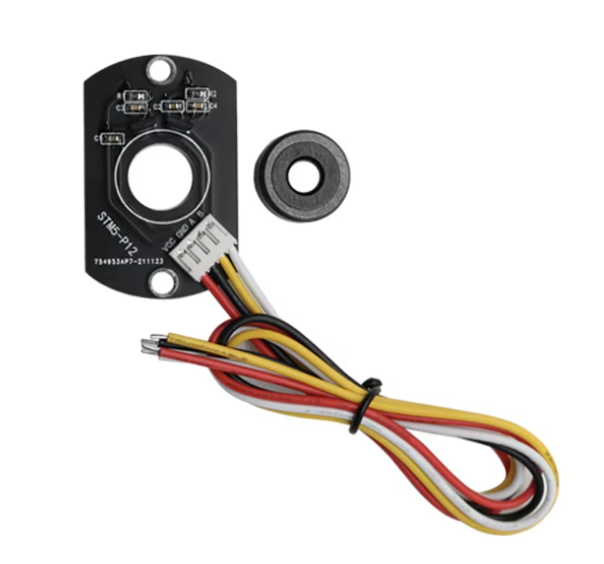
However, the PCB has a 4-pin JST PH 2.0mm connector on it. To plug this into the PCB, you need to solder on a corresponding connector, which is included with the kit along with heat-shrink.
First, strip all 8 of the wires down using wire strippers (or scissors, just be careful not to cut the wire). I would recommend leaving at least 3mm stripped, but generally just leave enough that it is easy to solder. Then, put heat-shrink on all 4 wires of the connector:
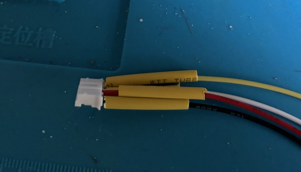
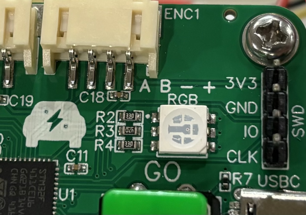
Now, you need to solder the appropriate wires to each other. On the circuit board you will notice that it says “A B – +” on the circuit board. This corresponds with the pins on the wire. So when you plug the connector into the board, its left-most pin will be A (which is the yellow wire), and so on. For example, with the connector shown above, yellow would be A, white would be B, Red would be +, and Black would be – when you plugged it in.
Now, just solder those to the corresponding wires on the encoder. Note that VCC is the same as “+” and GND is the same as “-“. So in the images for the encoder and connector shown above, you would:
- Solder red to black
- Solder black to red
- Solder white to white
- Solder yellow to yellow
Note that even though the colors are the same, the wires will still cross over each other because they are in a different order. Also, the colors on your wires may be different than mine so be sure to check them before soldering.
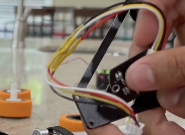
Finally, slide the heat-shrink over the solder joints and use a heat gun or lighter to heat it and have it cover up the exposed wire. Here is how it looked in the video tutorial after I soldered it:
Now, watch the assembly tutorial video:
Now, watch the run tutorial to learn how to run the vehicle:
Finally, learn how to program it through the programming tutorial:
How can this car be programmed?
It comes pre-programmed!
What modifications could be used on this design. Could I add a dc-dc converter before wiring meets the motor, therefore increasing voltage to the motor? Could I add capacitors in series to get more voltage, if so, where? Would I need resistors to the motor if I did this? Is it even allowed?
There is a dc-dc converter built into the board. Adding capacitors in series would just block all the voltage.
Is it possible to run two motors and individually control them, instead of one motor using this pcb, or is that not possible?
It is not possible with this PCB, but even if it were possible it wouldn’t make sense because
1. The motor utilizes the max amount of current the battery can supply
2. Sensorless brushless control is being used, which means the motors cannot be precisely controlled (on the scale of the EV) so if you’re trying to control the orientation precisely it will likely not work.
What’s the KV rating of the motor given in the kit?
1000