
 READ THE DESCRIPTION BELOW FOR PROPER USAGE


Install the Arduino library – Tektite RotEv Controller!
Battery Pack is NOT included!
Solder an XT30 Female connector onto an AA battery holder for use with these electronics! Note that this connector is polarized, so make sure to solder positive and negative correctly.
Min Voltage: 4.5V
Max Voltage: 15V
Do not use under 4 AA batteries or over 9 AA batteries!
Do NOT stall the attached servo!
The included 5V regulator is quite inefficient, so if a servo is stalling it will overheat and potentially burn and/or permanently damage the board. I have only tested with MG90s servos, but most 5V servos should work as long as they do not draw a lot of power. Don’t connect a BEC!
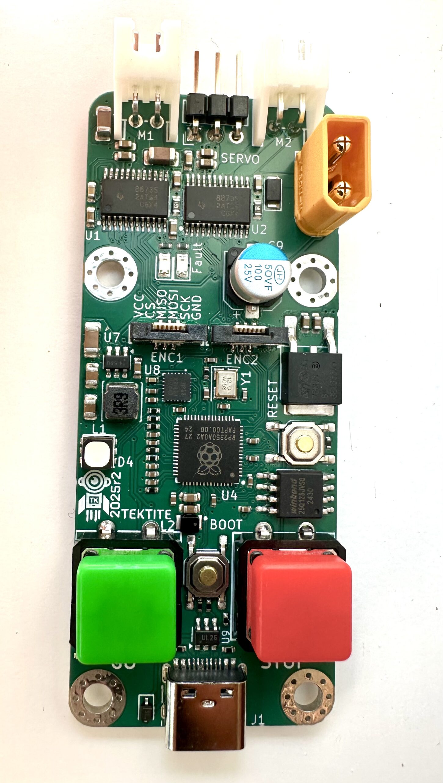
Make sure to connect the servo with S, +, – oriented correctly!
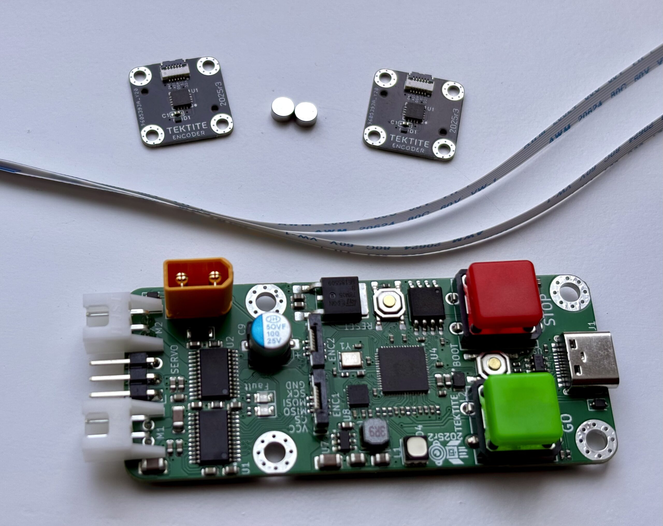
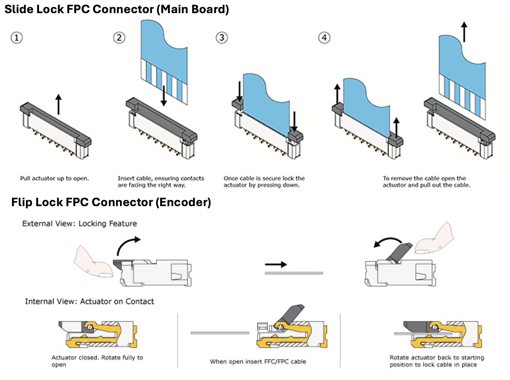
Using the FFC cables:
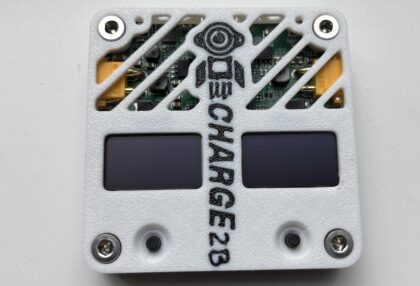
The connector on the board is a slide-lock connector. This means you have to pull the black part upwards, this may require fingernails or a flat head screwdriver to pull open, but be careful. Note that you need to face the contacts TOWARDS the text that says “VCC, CS, MISO, MOSI, SCK, GND”.
The connector on the encoder is bottom-contact. That means the exposed part of the connector should face TOWARD the board.
Use Type-A/Forward Direction 6-pin 0.5mm pitch FFC connectors. These are included, but you can purchase replacements or different lengths on Amazon here.
See the last product image for a visual guide on how to use the connectors.
Connecting motors
The motor ports are two-pin JST-XH female connectors. You need to buy JST-XH male connectors and solder them onto your motor. I am using these ones, but you can buy different lengths depending on your need.
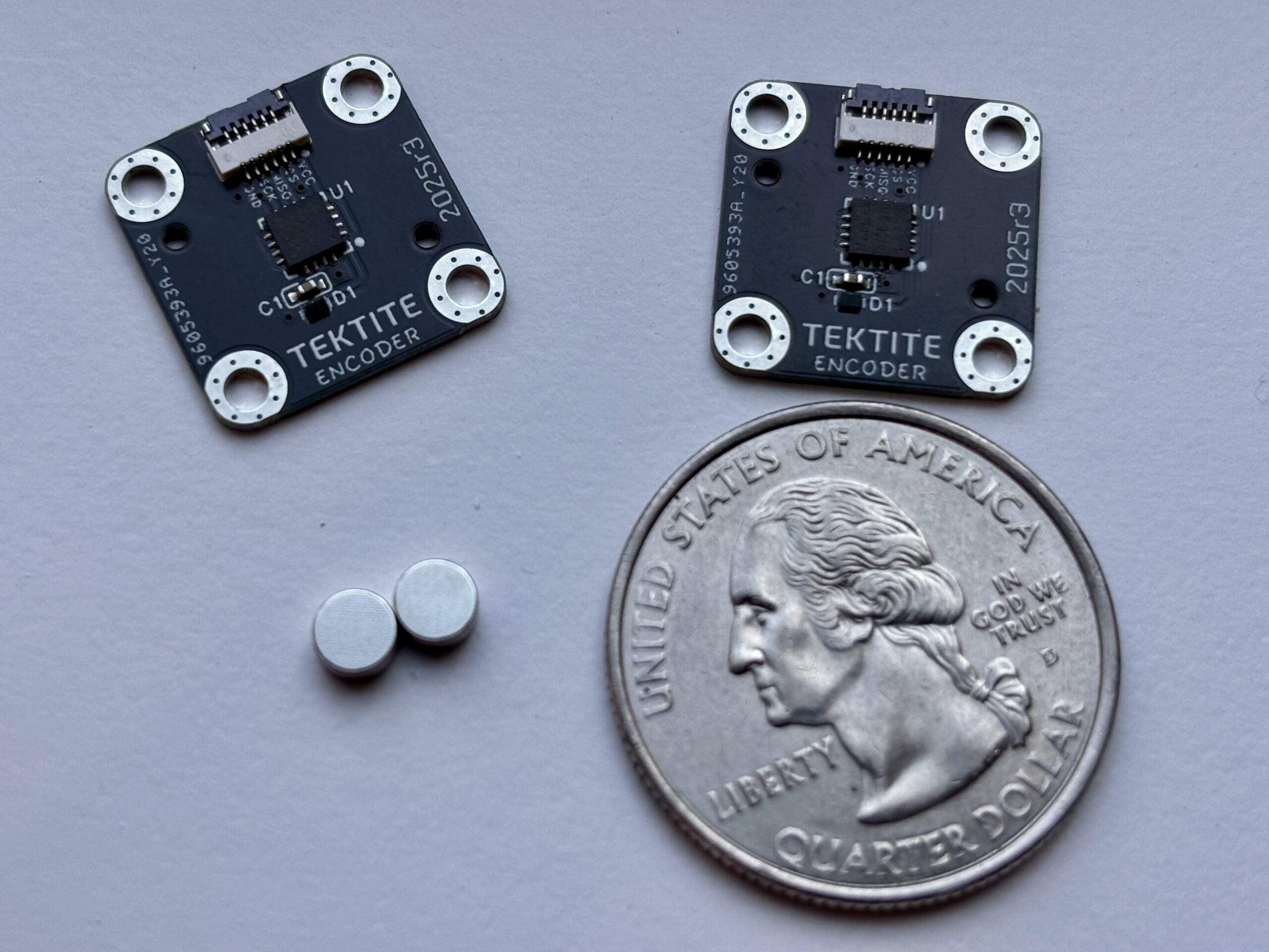
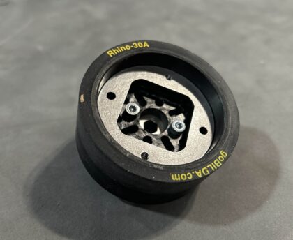
Using the MT6701
The included magnet must be 1mm to 2mm away from the encoder and centered perfectly above the center of the encoder (the black chip in the middle is the sensor). These are really easy to lose, so be very careful! The holes are M2 and spaced 12mm apart in a square.
You CAN connect the battery and your computer at once!
I didn’t include a switch on this board, so I just make my code so that it only runs when the GO (green) button is pressed and have it stop when the STOP (red) button is pressed. There are diodes preventing reverse current, so you can plug in the USB-C connector and program the board while the battery is connected.
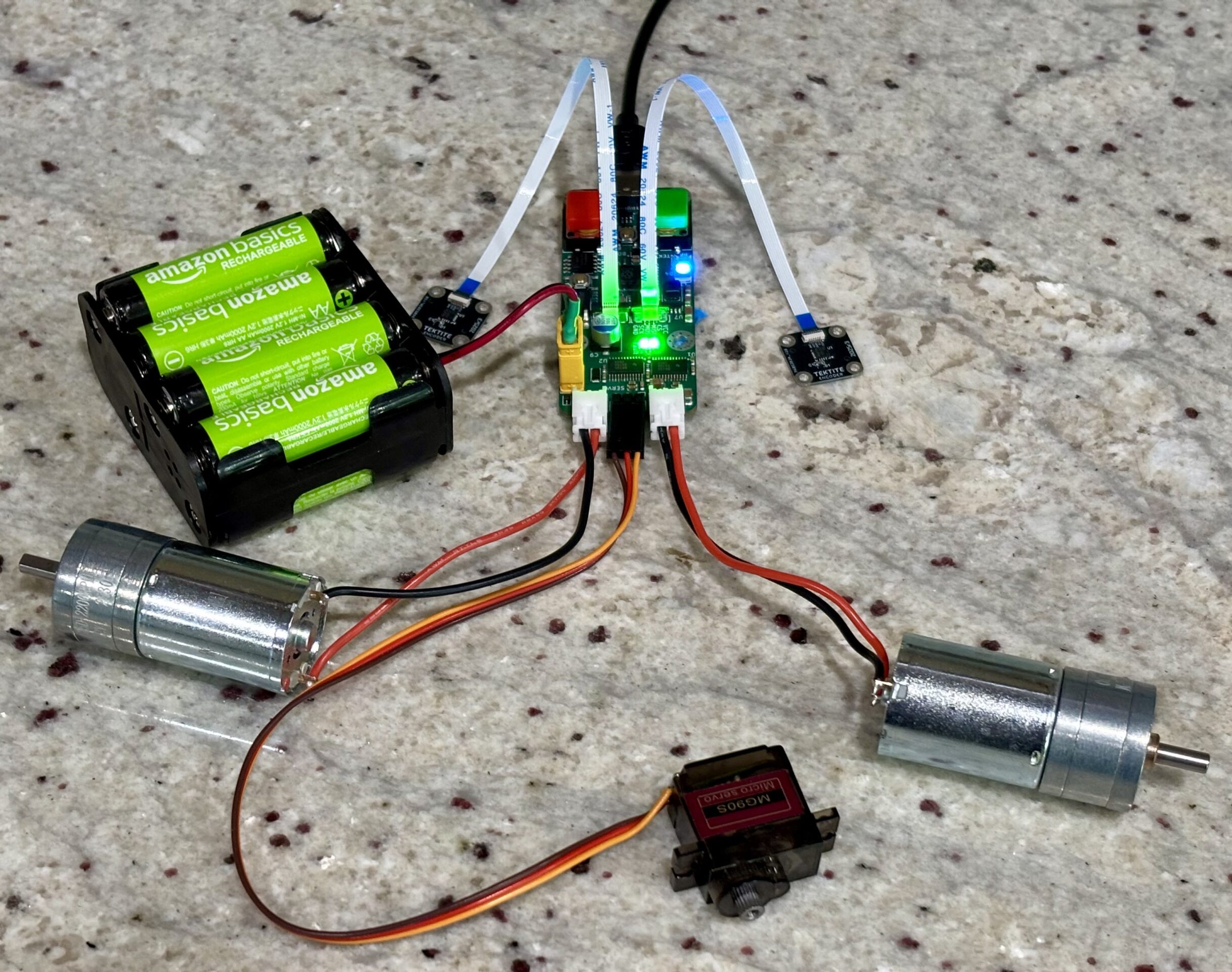
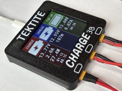
See the connection diagram (3rd image) for a full setup using this board!
Reviews
There are no reviews yet.